Charging and Gas Gauging for Mobile Devices
Operating effectively from a battery is a core requirement for all mobile devices. Good battery-powered behaviour is crucial for a product’s success. Battery-powered operation revolves around three major aspects:
- well-tuned system power consumption
- appropriate battery charging
- accurate “fuel gauge” or “gas gauge” prediction of battery state
For mobile devices, tuning of the system power consumption starts with defining the device use-cases and modelling the power consumption in its various modes. Normally this will include a very low “static power consumption” suspend state, when the device is not in use, as well as various dynamically-managed power states when operating in different modes. The topic of system power consumption is very broad, and will be addressed in a separate future blog.
The battery charging and battery gas gauging aspects of mobile operation are often overlooked or under-estimated in terms of system design and implementation effort. Especially for consumer products, marginal failures in either charging or gas gauging leads to great customer dissatisfaction: without reliable power supply your product is unusable. Problems like failure to detect the type of charger on 0.1% of plug-ins, or the product suddenly powering-off when indicating 15% power remaining, spell disaster for your product’s reputation when you’ve shipped one million units. These also lead to significant customer support costs. Issues like failing to stop charging when a device overheats can even present a life-threatening safety (and liability) issue, if a portable device is used in an environment such as a hot car.
All of these aspects require careful system design from the ground-up, at both hardware and software level. We’ll examine the basics of battery technology choice, hardware design criteria and decisions, typical system designs, software requirements, and examples of tricky edge-case problems. The goal is to highlight that charging and gas gauging are definitely subject to the “80/20 rule”: Getting 80% of the functionality takes 20% of the effort, but the remaining 20% of “final polish” takes more than 80% of the effort. A careful initial design, such as in the Open-Q series of Snapdragon™ development kits, is a great start down this road.
Battery Selection: Chemistry
Many parameters and features factor into the selection of appropriate battery cell technology. The first is the chemistry/technology of the cell itself. Most people are probably familiar with energy density, as shown in Figure 1. Various lithium chemistries are the leader here, giving most energy per unit volume or unit weight. Those will be an obvious choice for most mobile electronic consumer devices.
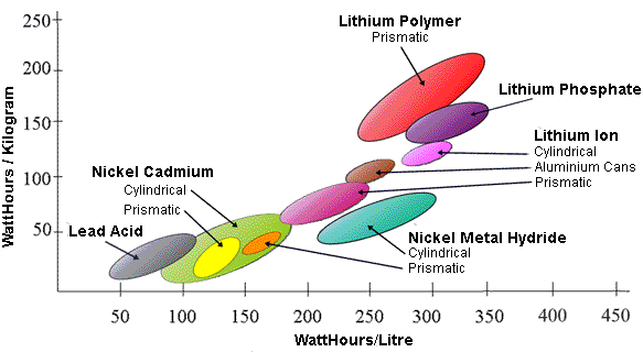
Figure 1: Energy density of various battery chemistries (courtesy of WikiMedia commons)
While important, energy density might not be the only decision-maker. Temperature can be an important factor for charging/discharging. Lithium batteries usually should not be charged below 0C, and generally are specified to be cut off from charging around 45 C. Generally they should not be operated at all above 60 C, and they contain a permanent thermal fuse to prevent catastrophic thermal run-away if other safety prevention methods fail. 60 C may seem outside your device’s normal operation, but on the seat or dashboard of a hot car, this can easily be reached within minutes. Consumer products for outdoor use (e.g. an IP camera) may face challenges with the low temperature limits too, requiring careful system design.
Aside from temperature, battery internal impedance and the rate at which they can discharge energy can also influence your cell choice. Where brief large currents (e.g. >4C[1]) are needed, another chemistry based on Ni or Lead may be more appropriate. (An example here could be power tools or systems with large displays).
In the case of Lithium chemistry (most consumer mobile applications), a variety of cathode compounds can be used for different properties and cell shapes/flexibility/configurations. These chemistries have subtly different properties for their voltage versus state-of-charge[2], internal impedance behaviour, and variation of stored energy and voltage with temperature. Gas gauge chip manufacturers refer to these as “Golden parameters” and will perform a careful characterization of any battery cell type to determine appropriate values to use when setting up your gas gauge chip for that cell.
Most commercial temperature range electronic mobile products today will use Lithium chemistry batteries, so we’ll focus on those.
[1] Notation refers to current corresponding to capacity. e.g. For a 1500mAh battery, 2C is 3 Amps.
[2] State of Charge is the percentage of total energy remaining in the battery, often referred to as “current capacity”.
Charging
For a particular battery chemistry, there will be an appropriate paradigm for charging that cell. For Lithium-based chemistries the method involves three specific stages: pre-conditioning, constant-current, and constant-voltage charge stages.
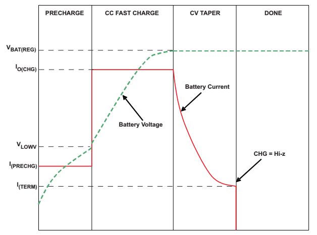
Figure 2: Lithium Charging Profile (courtesy of Texas Instruments (bq24072)
Lithium-based cells can be permanently damaged if they are discharged beyond a specific low voltage, for example by being connected directly to a resistive load like a light bulb. To prevent that damage, most Lithium battery packs will contain a small “protection circuit” PCB which incorporates a low-voltage cut-out circuit. When the cell voltage falls below ~2.5V, the protection FET opens and the apparent voltage at the battery terminals falls to 0V. Before charging a cell in this condition, it’s necessary to “pre-condition” the cell by applying a small trickle-charge current, usually 100mA. To detect whether a battery is connected at all, it will be necessary to apply this current for some time (e.g. several minutes), then remove the current and check for battery voltage. This process should continue until the battery reaches its minimum conditioning voltage as specified by cell vendor, usually 2.8V to 3.0V.
As we will see in the next section, most system charger designs allow some or all of the externally-supplied charger current to power the system (so called “by-pass“) instead of being directed into the battery as charging current. Unless your system can operate (boot and run software) entirely on external-power, this pre-conditioning charge of the dead battery must be entirely managed by the charger hardware itself.
Having reached the constant-current charging section, the charging current can then be stepped up, usually to a maximum of about “1C“. This is a current (in mA) roughly equivalent to the cell’s rated capacity in mA-hours. Newer chemistries can permit higher charge currents (and thus shorter charge cycles), especially if the cell temperature during charging is carefully controlled. During this portion, the cell’s voltage will slowly rise. The maximum charging current will impact your choice of external charger, cabling, connectors etc.
The control of charge current with temperature is the subject of several safety standards, including IEEE 1725 and JEITA. Charger circuitry itself can be damaged if subject to excessive load currents at high temperatures, so the charger circuits usually incorporate thermally-controlled throttling based on die temperature. More importantly though, Lithium-based cells can be subject to catastrophic thermal run-away if charged (or discharged with large currents) at high temperature. To prevent the risks of fire and melt-down, the cells usually contain an internal thermal fuse (which permanently disables the cells) at high temperature (usually ~90C). Well before this stage is reached, the system must turn off the charge current when the cell temperature exceeds limits. The cell manufacturer will supply the temperature limits, but these usually stipulate no charge above 60C or below 0C. In the past these have been hard on-off charge limits, but the JEITA standard (required in Japan and becoming more wide-spread as a de-facto standard) has a much more complicated profile of charge current derating based on cell temperature (see Figure 3).
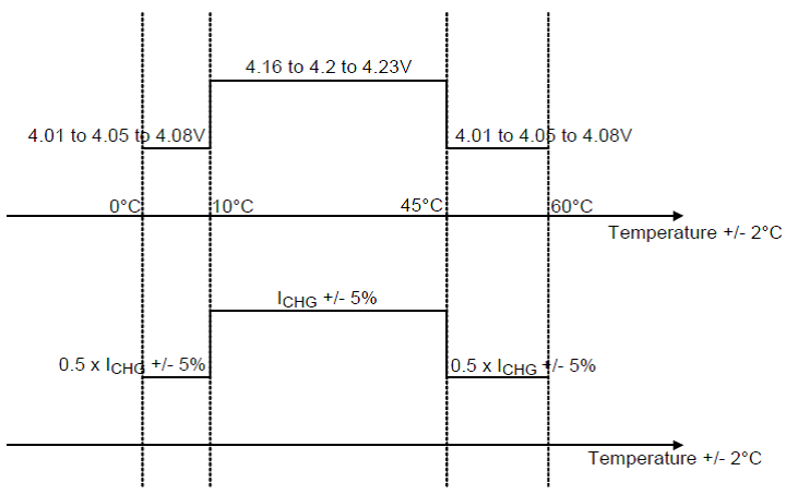
Figure 3: JEITA Charging Standard, Voltage and Current (courtesy of Richtek Technologies, richtek.com)
Having this fine-grained control over charge current often requires a combination of software and hardware, such as driver-level adjustments to charge thresholds. Relying solely on software is not possible, though. To prevent excessive battery discharge and damage to other components at high temperatures, your system may need to shut down in hot environments such as a hot car. Booting and charging should then be prevented when no software is running, or in the case of software malfunction. Consult IEEE 1725 and IEEE 1625 for safety-critical requirements in this area.
The temperature of the cell is usually monitored via a dedicated thermistor. This is often incorporated inside the battery pack itself, especially in systems where the battery is somewhat isolated from main circuitry. This can raise the price of the battery though, so in designs without an in-pack thermistor careful system thermal design is needed.
Full charge, termination current
At the end of the constant-current charge portion, the cell will be approaching its maximum voltage, around 4.1 to 4.2V. At this point, the charger must limit its applied voltage to its cut-off voltage, while the charging current inherently slowly reduces. The voltage selected for this constant-voltage charge section has an impact on the cell’s life, with accelerated aging when too high a voltage is used. Too low a constant-voltage threshold results in sub-optimal full charge capacity, so a trade-off is made here, usually selecting around 4.15 to 4.2V.
Cells will be chemically damaged if subject to a permanent external charging voltage as well, so the chargers terminate their charge cycle and remove applied voltage entirely when the charge current falls below a certain threshold. This level is usually referred to as the “taper current”, and is another key parameter when tuning your charger circuitry.
If your system stays plugged into the charger, then the battery will be subject to periodic “top-up” charge cycles when the cell has discharged by a certain % charge or voltage. The charger system usually ensure that these top-ups are mini charge-cycles, with constant-current and constant-voltage sections.
Charger system designs
The system charging circuitry is usually either a dedicated charging IC, or is incorporated within the system’s Power Management IC (PMIC). When included as part of the PMIC, the charging system design may define a main node from which all system power derives. This node can be supplied from current bypassed from the external charger, and in some designs will also include the ability to supplement system current from the battery at the same time. Depending on system power load, a plugged-in system may be charging the battery at high rate, charging at a throttled rate (because considerable power is being drawn for system operation) or using all the power from the external power while also discharging the battery at the same time. See Figure 4 for mode examples and bypass/supplementation of the charging current. Good system designs here can greatly improve the user experience in different modes of your system.
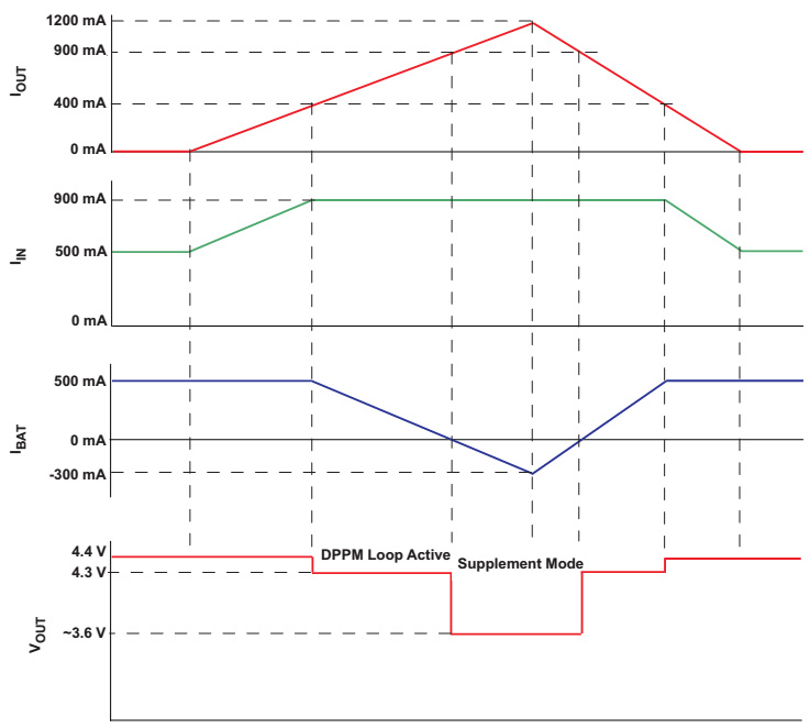
Figure 4: Charger system bypass and charge current throttling (system supplement).
Courtesy of Texas Instruments (bq24073)
The charger subsystem in the Snapdragon™ family Power Management ICs from Qualcomm® includes SMBB™ technology which can convert the charger circuitry to a boost mode, to generate 5V into the charger power node, in order to power the high-drain camera flash LEDs. Also included is “Bharger™” technology to generate smaller-current 5V supply for supplying VBUS to the USB connector, necessary for operating in USB host mode.
USB type-C includes a Power Delivery specification which negotiates higher charger input voltages over a dedicated charger protocol channel, for faster charging. Qualcomm supports a wide variety of technologies and techniques for Quick Charge™, including Intelligent Negotiation of Optimum Voltage (INOV) based around the principles of charging voltage negotiation. (See https://www.qualcomm.com/products/snapdragon/quick-charge.) Supplying higher input voltages will improve power transfer rates and can greatly reducing charging times.
Gas Gauging
The final component of a successful battery-powered system is the ability to gauge how much energy remains in your system’s battery at any time. This is referred to as “gas gauging”. For successful gauging it is important for users that your system does not die unexpectedly, while at the same time stretching maximum energy out of the battery. Having your system fail suddenly due to low voltage can be both annoying and hazardous, potentially leading to data corruption or loss. Some devices, like those with an Electro-Phoretic “E-Ink” screen can appear to be switched-on while the battery is actually dead, leading to user confusion, complaints or customer-support calls.
There are two basic principles to gauging the energy in the battery: mapping the battery’s voltage to the current state-of-charge, and “what comes in must go out”. The latter sounds simple, and is what is known as “coulomb counting”. Circuitry integrates the current flowing in/out of the battery, to maintain a measure of the charge (and thus energy) in the battery (Figure 6). This has its challenges in practice, including:
• determining the initial state-of-charge of the cell
• self-discharge of the battery due to internal resistances and leakages
• energy loss during discharge due to internal battery impedance
• accurately measuring discharge at all times, including small leakages while the system is powered off, and the energy contained in short spikes when large subsystems are powered on or off
Mapping the battery voltage to its state-of-charge also has its challenges:
• voltage to state-of-charge varies depending on cell chemistry (Figure 5)
• battery voltage depends on the cell internal impedance: the voltage drop can be substantial under heavy current load
• hysteresis due to charging or discharging: the voltage can be higher or lower than the open-circuit “relaxed” value depending on how the state-of-charge was reached
• the open-circuit voltage increases with temperature, drops at lower temperatures
Due to these challenges, carefully tracking the battery’s impedance is crucial to effective gas gauging. This impedance changes with cell conditions like aging and charge/discharge cycle count, so for best accuracy a “fingerprint” of impedance is maintained for a particular cell. This implies that when the battery is changed (e.g. if your system has a user-accessible battery pack) then your system must recognize and re-evaluate the situation for the new battery pack.
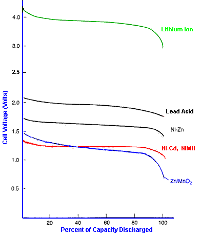
Figure 5: Typical Open-circuit Voltage to State-of-Charge curves (courtesy of mpoweruk.com)
Overall, effective gas gauging requires combining the open circuit voltage measurements together with coulomb counting. The open circuit voltage (measured at very low system discharge current, such as during a “suspend” or “sleep” state) is converted to state-of-charge based on standard profiles given the battery’s known chemistry as shown in Figure 5.
The open-circuit voltage measurement can provide a reasonably accurate “point value” of the battery’s state-of-charge, especially if the system has been quiescent (or relaxing) for some time, allowing any hysteresis from charging or discharging to subside. This measurement helps plot the cell’s “maximum charge capacity” against its factory-default maximum charge capacity. Over time, the maximum charge capacity will drop as the battery is able to hold less and less charge.
Because your system use-cases may not often allow effective measurements of open-circuit voltage (e.g. continuously changing system current load), coulomb counting is used to track energy increase or decrease during active periods. This can be combined with knowledge of the battery’s internal impedance to track state-of-charge by battery voltage.
Gas Gauging System Designs
Doing this all effectively either requires complex driver software, or leveraging the knowledge and development efforts of silicon manufacturers who have designed gas gauging hardware and firmware to implement these algorithms effectively. This can be done by designing gas gauging:
- into the battery pack itself (as is done for example in laptop batteries or higher-end battery packs)
- as a discrete gas gauging chip on the power subsystem PCB
- as a integrated component of the system’s PMIC
The one which involves least system integration effort and typically fewer integration problems, is the in-pack gauging. This has a number of distinct advantages, including ease of tracking per-pack aging data and impedance, ease of dead-battery charging and boot-up (since cell capacity can easily be retrieved from the pack in low-level bootloader software) and very low system integration and debug effort. The BOM cost of the battery pack is high, however.
The discrete gas gauging chip solution (see Figure 6) can provide excellent gauging performance, and can provide access to parameters like “minutes until empty”, based on a window-averaged system power consumption. Solutions from providers such as Texas Instruments encapsulate complex algorithms such as “impedance track” and provide customizable features such ensuring the reported state-of-charge is as close to monotonically decreasing as possible. (It can be confusing to end-users and lead to complaints if remaining capacity suddenly jumps from 10% to 20% after a system relaxation period). As we will see next, sometimes the uncoupling of gas gauge from charger IC can lead to some tricky edge-cases, however.
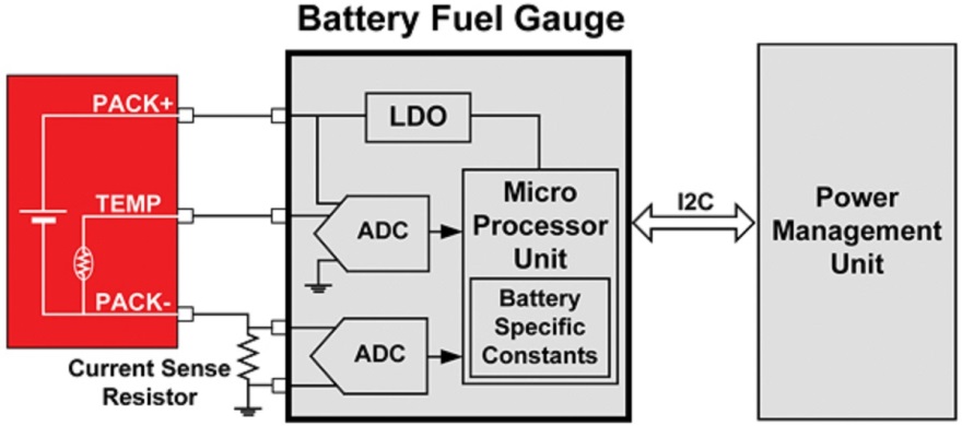
Figure 6: Typical external fuel gauge with coulomb-counting. Courtesy of ecnmag.com.
Using a highly-integrated system PMIC as a combined charger/gas-gauge solution can allow full customization, and can provide the lowest system BOM cost, component real-estate and PCB complexity. Solutions which include road-tested driver software can help reduce the software development and tuning efforts, especially when you stick closely to the reference designs.
Paired System-on-Chip and PMIC solutions, such as Qualcomm’s highly-integrated Snapdragon™ family of processors, provide a rich feature set for charging, gauging, and system power conversion. These include the ability to drive user feedback LEDs (useful in the case of dead-battery-charging), internal battery voltage boost technology, and important built-in over-voltage protection on the power inputs.
Qualcomm’s integrated solutions, such as the APQ8016 together with its PMIC PM8916 as designed into Lantronix’ Open-Q 410 SOM and reference carrier board solution, come complete with BSP support for charging and gauging solutions. This reduces integration efforts to tuning needed for your product’s selection of battery cell and power use-cases.
Gas Gauge Parameters Definition and Tuning
Whether you use discrete gas gauging components, or a PMIC-integrated solution, you need to define the gas gauging parameters specific to your system. The most important of these parameters is your system’s “Empty Voltage”. This voltage is derived from your system’s “Dead Voltage”, in turn defined by your system’s hardware. The dead voltage is the minimum battery voltage at which the system can operate properly. Various system components feed into this decision, including the input specs for your voltage regulators and their buck or boost configuration. Above this dead voltage, you need to account for tolerances in voltage inputs, variations in temperature, gauging error, and spikes that happen when components switch on or off. The end result will be the safe “Empty Voltage” at which your system must immediately power off (see Figure 7).
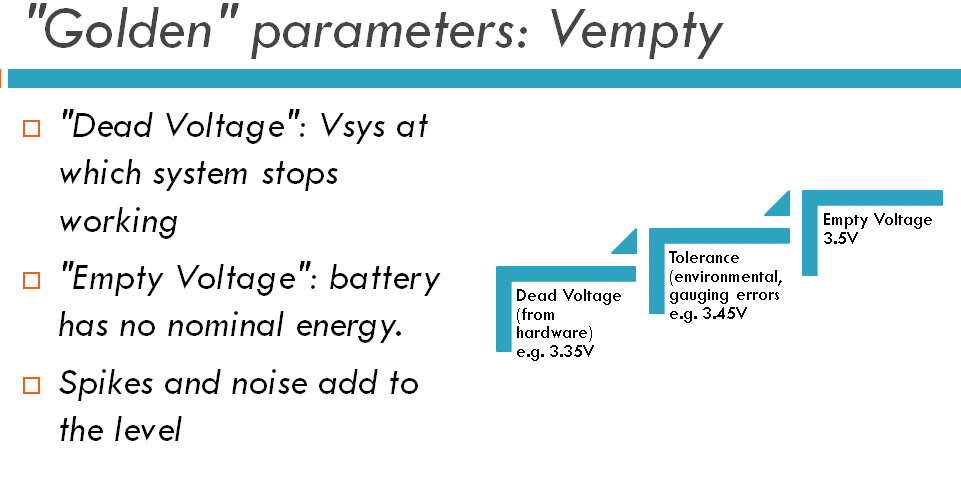
Figure 7: Empty Voltage Definition
Having defined your system’s Empty Voltage, you then need to specify the system’s Reserve Capacity. This is a gauging parameter that ultimately defines when your battery is at “0% capacity”. At this point, your system should shut down cleanly. Doing this ensures your users are properly informed of system shutdown, and that no data corruption or loss exists. The reserve capacity is defined in terms of energy, and is based on the headroom of run-time needed to respond to the battery level and perform the shutdown. Delays in sampling, time required to give feedback, flush data-stores, and shutdown are all inputs to this parameter.
Without correctly defined Empty Voltage and Reserve Capacity, your system will be subject to brown-out, where it unexpectedly dies, one of the most troubling and disruptive faults for your end-user.
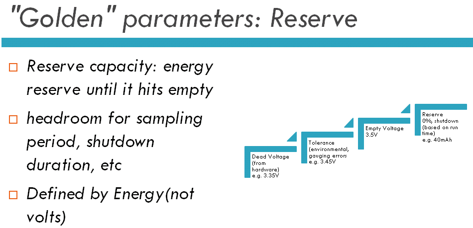
Figure 8: Reserve Capacity Definition
Summary: A Tricky Edge-Case
As a final round-up, here is one example of a complicated edge-case in system charging/gauging.
A system had discrete charger IC providing source system bypass and charge current throttling, allowing external input current to either charge the battery or supply the system power rails. The discrete gas gauging IC tracked state-of-charge, and also maintained a measure of the cell’s full charge capacity, based on a combination of open-circuit voltage and coulomb counting.
Charging was permitted from either a dedicated charger (1 amp) or from USB source (less than 500 mA). When the system’s LCD panel was on and playing video, the system power requirement was about 800 mA. With the LCD off, system power requirement was less than 100 mA, so USB power input could effectively charge the battery with up to 350 mA. When the system was plugged into USB power source and the screen was toggled on and off, the battery would switch from charging to discharging (throttled charging with system supplement).
The gas gauge IC monitored the battery pack’s full-charge capacity (how much the battery can hold based on aging and cycling). This amount of energy the fully-charged cell could hold, was used in calculations/predictions for shutdown capacity. It detected a fully-charged situation whenever the cell voltage was measured within 85% of ‘full’ (>4.0V), and when it saw averaged charge current drop below the termination current.
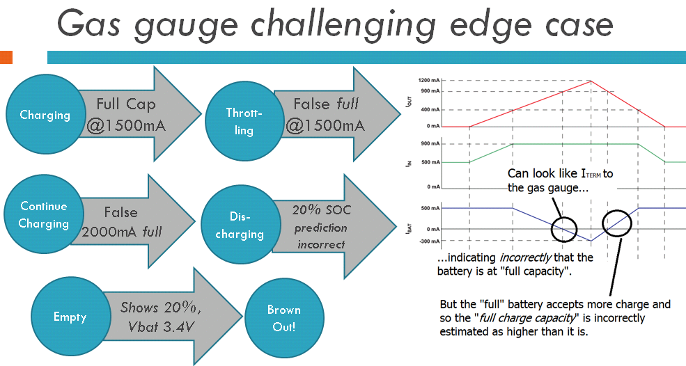
Figure 9: Challenging Gauging Edge-Case Round-UP
Unfortunately, when the user turned on the screen at an inopportune moment, the gas gauge IC would detect the charge throttling (caused by separate charger IC) as a “fully charged” situation. Averaged charge current dropped to 0 mA, so therefore the gas gauge assumed the cell was full (100%). Then, when the screen was turned off, charging resumed and the gas gauge ultimately calculated the cell as holding more energy than expected.
The result was that when the system was later unplugged and discharged, the incorrect estimate of full-charge capacity resulted in a system brown-out and immediate shut-off, even though the user was told there was 20% energy remaining. Preventing this situation needs careful production tuning of your parameters, good gauging algorithms, coordination between charger and gauging, and and good design of the system use-cases. (For example, was charging at <500ma via USB necessary?)
Author
Ken Tough, CEng is Director of Software Engineering at Intrinsyc Technologies. He has worked in the embedded software and electronics industry for over 25 years, in fields ranging from defense to telecommunications to consumer products. His experience in battery-powered devices was gained in large part through commercial eReader product support by Intrinsyc to major ODMs.


