Device Driver Development Overview In Unified Extensible Firmware Interface (UEFI)

Today’s embedded systems come to market with increased functionality and more complex features than ever before. With these more powerful capabilities, there are increased requirements on embedded device design for: Security, greater memory capacity access, peripheral address space access immediately on power-on (at the bootloader level), increased boot performance, and greater User Interface (UI)/graphics support at an early stage in the booting/power-up. UEFI satisfies all these requirements and more! UEFI is rooted in a specification that defines an interface between an operating system (Eg: Windows, Linux) and the device firmware.
UEFI is commonly used in Windows based systems. However, recently UEFI found its way into Linux and Android based embedded systems as well. Recent versions of Ubuntu have also been deployed with UEFI based solutions for PC’s. With the overall increase in the use of UEFI in embedded systems, let’s have a look at the driver stack of the UEFI and how you can harness its generic design for customizing your embedded system development.
In addition to the common U-Boot bootloader for Linux/Android, sometimes the Little Kernel (LK) bootloader can be seen used in various embedded systems. For example, platform software based on the Qualcomm Snapdragon 820, 410, and 626 development kits use the LK bootloader. The LK bootloader is also known as an application binary loader or ABL. Recently, there has been a move from the LK bootloader to the UEFI based loader as the ABL based on the EDK2 project (https://github.com/tianocore/edk2). The UEFI implementation is actually split into two parts:
- Core secondary bootloader code – consisting of drivers and code specific to a particular chipset (implemented by Qualcomm).
- Apps bootloader containing code to access the core secondary bootloader driver API’s and applications like Fastboot (Open source code for Android).
EDK2 project is a firmware development environment or a framework for UEFI specifications. It implies that any code based on UEFI specification can be developed by using the EDK2 project repository. EDK2 is now present in many recent Qualcomm platform software including the Open-Q 835 HDK, Open-Q 660 HDK, Open-Q 845 HDK, as well as other platforms available from Intrinsyc Technologies.
UEFI is much more modular than LK and provides the support for abstracting the underlying hardware from the operating system. This blog is about how the drivers for various peripherals are stacked up and how we can modify existing drivers and libraries and/or write new ones in order to customize and add new features to harness the power of this architecture.
To begin with, let’s understand some key concepts in UEFI that are important in driver development:
- UEFI objects: These are components that manage the state of the system. They may include devices, memory, etc
- UEFI system table: This is a very important data structure of the UEFI. The table contains information about the system configuration and UEFI services, and acts as an entry point into various UEFI services. Information in the table is required by all UEFI components. Although you don’t need to understand its entire design; understanding a few basic concepts like GUID and protocol services as explained below should be good enough to get started.
- Handles database and protocols: These are handles which are registered and can be used to obtain various services.
- UEFI supports dynamic memory allocation and event-based code flow.
The four concepts above are key considerations for this blog. That being said, UEFI has numerous additional useful capabilities and features – such additional information is available online at the UEFI Wiki page (https://en.wikipedia.org/wiki/Unified_Extensible_Firmware_Interface).
There are various peripherals in an embedded system and UEFI has a protocol service for each one of them. A protocol service can be a UEFI driver consisting of functions and data fields. Each protocol service is associated with a globally unique identifier (GUID) and can be referenced or identified by using this GUID.
With a variety of peripherals and their drivers, a developer needs a table or a database which contains references to all these drivers. For exactly this purpose, the UEFI bootloader also contains a Handles database which includes a collection of all the necessary driver handles.
For example, an I2C based driver stack would have an GUID associated with it. Hence a developer simply needs to use the GUID for I2C and access all the functions of the driver for IO operations through it. Now, the protocol service mentioned earlier would be the I2C driver here and the core of UEFI will maintain the mapping of the driver, its functions, and the GUID’s in the tables and databases mentioned earlier.
UEFI code organization from driver to application bootloader:
Typically, the drivers are stacked in three or more layers depending on the peripheral (See Figure 1).
The first layer is a very low-level driver complying strictly with the UEFI which will deal with the intricacies of the peripheral. There are various helper functions that this driver will export which the library code in the UEFI compatible loader will use to perform IO operations. This driver would typically be provided by the vendor.
The second layer consists of the library code. This library code will use the driver helper functions and control the peripheral.
The third layer will be implemented as a part of the application bootloader which is also known as the ABL in case of older Qualcomm Android-based systems.
Let’s walk through an example of a chip information driver and then based on this information we can see how we can develop a similar driver for other peripherals.
Chip Information Driver-Library stacking:
Generic stacking of various software components and information flow:
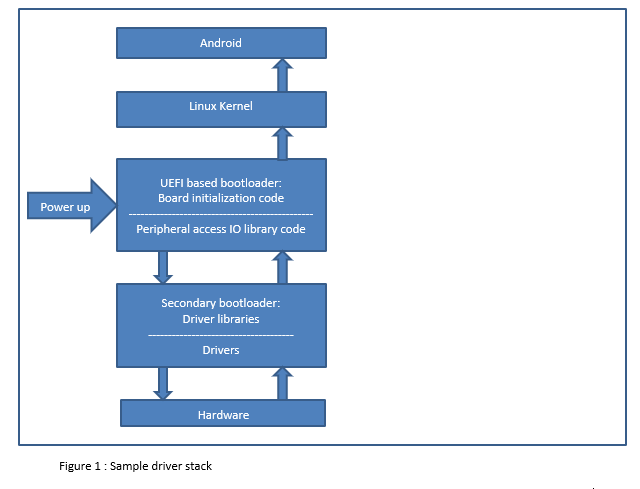
On boot up, the UEFI bootloader will run board initialization code which will request for the necessary information like the chip information. The UEFI bootloader can also request for IO operations. These requests are then passed on to lower layer drivers / primary bootloaders as shown above and the necessary information is passed back to the UEFI. Once this information is available UEFI can pass on this information to the Linux Kernel via various methods like the commandline. From the commandline, this information can be picked up by any driver and made available to the Android system via sysfs and procfs entries.
Detailed information on how passing of data can be implemented:
An SoC/SoM/Chip can have some key information like the chip serial number, chip version, chip family, etc. All this information is used by driver in the kernel to perform appropriate settings.
The lowest driver first reads all this information. The implementation of this read functionality is highly device/chip specific and involves dealing with the intricacies of the chip. This driver would be typically implemented by the semiconductor vendor. This driver would have a 128 bit globally unique identifier (GUID) associated with it. This is a very important ID since it acts as a handle in accessing the read and write functions provided by this driver.
The next software component in this stacking is the library code. This code basically is a wrapper over the driver API interface. The library functions mainly deal with function pointer translations and make it easier to read and write the data from the driver interfaces.
Sitting on top of this library code would be the application bootloader. This bootloader would use the GUID to invoke the driver code via the library API to perform the IO.
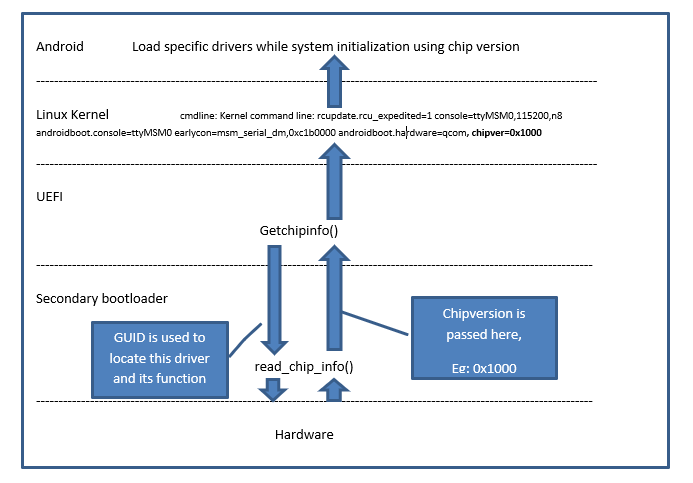
Consider a driver in the kernel wants to read the chip version and load an appropriate driver based on it since different chip versions may have different features. To do this, a developer needs to add code in the application bootloader. Typically, there will be some board specific code that will run when the application bootloader code starts to execute. Developers can implement a function like getchipinfo() to invoke the chip info library, and in turn the chip info driver code, for performing IO operations.
Implementation of getchipinfo:
- First step should be to locate the protocol service chipinfo implemented by the semiconductor chip vendor. There are helper functions to locate this protocol service. These helper functions should also be typically implemented by the vendor. Locating the protocol service or the lower level drive function is done with the GUID.
- Once the protocol service is located, a handle or a pointer is returned. Using this pointer/handle, the functions implemented in the library code can be invoked. Read information can be passed on to the calling function (function in the application binary loader) by passing an argument. Which is in this case the chip version.
- Once we have the chip version in the bootloader, the bootloader can pass on this information to the kernel via command line arguments or by writing into some non-volatile memory so that it can be read later
Implementation ideas on similar lines:
- UEFI provides a platform information stack similar to chip information stack described above. Customers/developers can implement their own modifications in this stack to add their own platform-specific information, such as security keys, network addresses, etc.
- Similar to above implementation, this information can then be retrieved at runtime and can be passed on to the kernel via command-line and then used to load various device drivers and or used by various modules to determine the startup flow of the system.
Tips for developers:
- As mentioned earlier, UEFI has many driver stacks that are already written, documented and tested. To implement a new feature, a developer can duplicate any of the existing driver stacks and then modify the code as per requirements. This will help reduce the errors in integration.
- Another approach is starting developing their own driver stack by studying the various build makefiles of any of the existing driver stacks, writing new makefiles for their own stack and building and testing them.
- Finally, the Apps bootloader needs to be modified regarding this new driver stack and necessary code modifications in the form of build makefiles. Inf files need to be completed to access the driver API’s of the newly added driver stack.
Summary:
Use of the UEFI bootloader mechanism opens up a range of possibilities for structured development and customization for vendors, system integrators, OEMs, and their enthusiastic developers who want to customize their products. For example, one can make use of chip variant information to load only specific drivers, decide on which code to run on which chip, store some private device-specific information in the memory and read it to validate, identify, secure the device, and so on.
While one can always make use of existing features like the chip version, other developers or companies can implement their own driver for a custom peripheral or store additional security information in the memory and verify the authenticity of their product at runtime.
The possibilities are endless!
Author
Chaitanya Dhere is an Embedded Software Developer at Intrinsyc Technologies and has experience in Linux kernel, device drivers, UEFI, board bring up and system software development on various Embedded platforms.
